How to size an air compressor.
To size an air compressor, add up the average air use of each tool and process, write the flow and the pressure on the same basis, read the load profile, check the receiver and the leaks, allow for growth and measure before you buy.
Eight questions before you size.
Work through the same eight questions for every compressor you consider, and write the answers down.
| Step | What to settle |
|---|---|
| 1. Air demand | What does each tool and process use on average, and how often does it run? |
| 2. Flow and units | Is every flow written in the same unit and at the same reference conditions? |
| 3. Working pressure | What is the lowest efficient pressure, and what is lost between the compressor and the point of use? |
| 4. Load profile | How does demand change over the day, and how will the compressors follow it? |
| 5. Air receiver | How much stored air covers the short peaks? |
| 6. Leaks | How much of today’s demand is leakage? |
| 7. Growth | What will the plant need in the next few years, and how would capacity be added? |
| 8. Measurement | What have you logged before you buy? |
Your air demand.
Add up what the tools and processes actually use, not what they could use at their maximum.
Compressed Air Challenge Fact Sheet #1 (May 2026) adds up the requirements of each tool and process operation at the site, with load factors taken into account. The figure to add up for each one is its average air consumption, not its maximum requirement.
For example, a tool that uses 100 L/s (6 m³/min) while it runs, and runs 30% of the time, adds 30 L/s to the average. High short-term demands should be met by air stored in an air receiver, which is step 5.
The same fact sheet lists four air quality levels, plant air, instrument air, process air and breathing air, and says higher quality air usually requires additional equipment. Settle the quality with the demand, because it changes what the compressor has to be completed with.
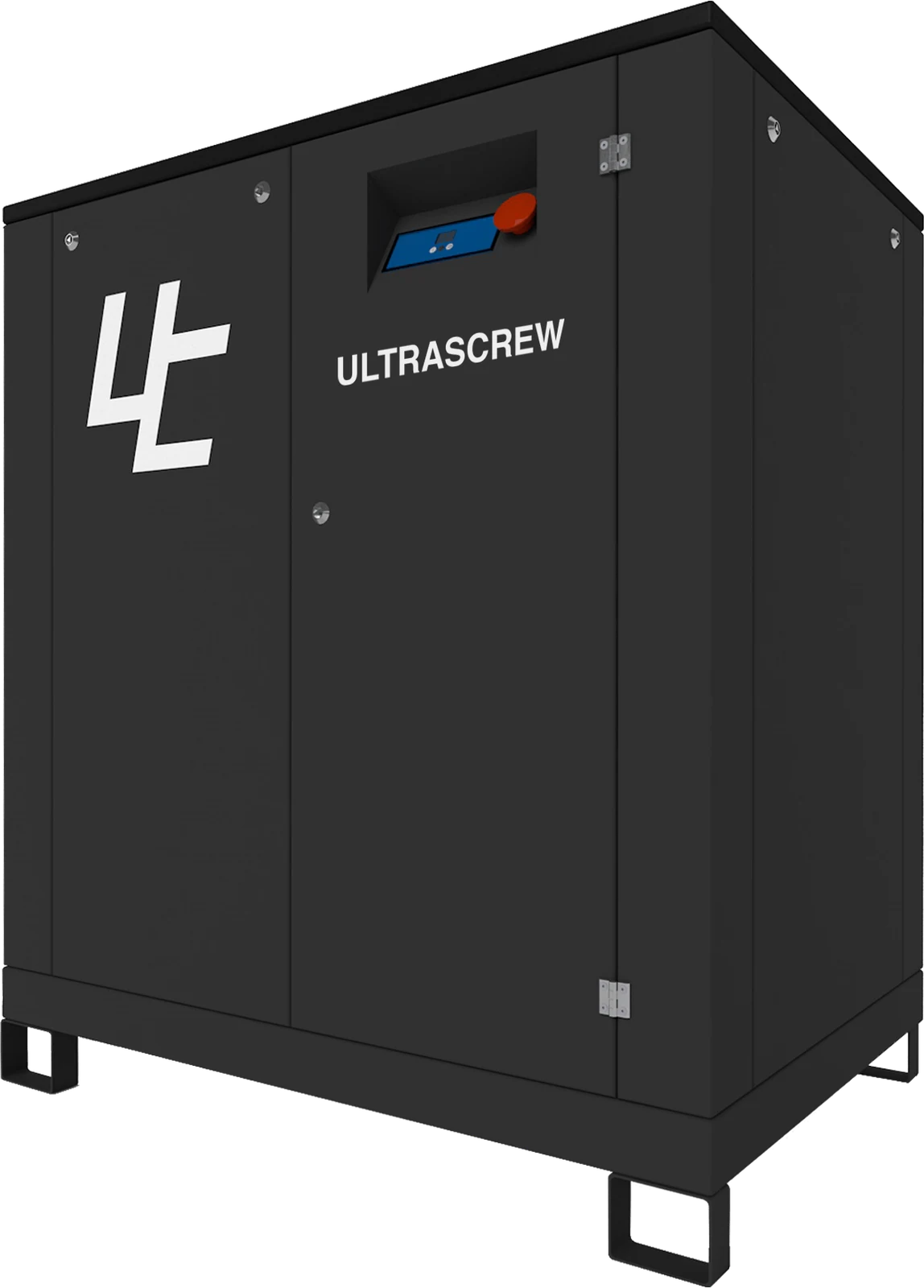
Fixed speed ULTRASCREW compressors in ULTRAAR ME run from ULTRASCREW 4 FSD to ULTRASCREW 132 FSD, 4 to 132 kW, at 22 to 1,170 Nm³/h at 10 bar (370 to 19,500 L/min) and 38 to 840 Nm³/h at 13 bar (640 to 14,000 L/min), per compressor, as listed in the ULTRAAR ME datasheet.
For ULTRASCREW DS VSD, the Ultra Controlo engineering team sizes the configuration and sends a quote.
The flow, and its units.
Write every flow in one unit, with the reference conditions it is stated at.
The US Department of Energy sourcebook (third edition, 2016, p. 83) defines actual capacity, also called free air delivered (FAD), as the quantity of gas actually compressed and delivered to the discharge system at rated speed and under rated conditions. FAD is a quantity; litres per second, cubic metres per minute and per hour, and cubic feet per minute (cfm) are the units it is written in. The conversions are in the table below.
A flow means little without its conditions. The sourcebook defines standard cfm as the flow of free air measured and converted to a standard set of reference conditions, 14.5 psia, 68 °F and 0% relative humidity (p. 84). Fact Sheet #8 says manufacturers may test under different standard conditions, that standard conditions should be 1 bar, 20 °C and dry, and that performance at site conditions will differ from test data because of ambient temperature, pressure and humidity.
The ULTRASCREW datasheet states that air flow is measured in accordance with ISO 1217:2009, Annex C, and that its values refer to 1 bar absolute, 0% relative humidity and 20 °C inlet air temperature.
The ULTRAAR ME datasheet lists each fixed speed ULTRASCREW in Nm³/h and in L/min: ULTRASCREW 37 FSD lists 322 Nm³/h at 10 bar, which is 5,370 L/min, or about 89.5 L/s.
Converting between flow units.
Read across: one unit in the first column equals the figure shown in each of the others. Arithmetic from the National Institute of Standards and Technology factor of 0.4719474 L/s per cfm.
| One of | L/s | m³/min | m³/h | cfm |
|---|---|---|---|---|
| 1 L/s | 1 | 0.06 | 3.6 | 2.119 |
| 1 m³/min | 16.67 | 1 | 60 | 35.31 |
| 1 m³/h | 0.2778 | 0.01667 | 1 | 0.5886 |
| 1 cfm | 0.4719 | 0.02832 | 1.699 | 1 |
The working pressure.
Size at the lowest efficient pressure the end uses allow, plus what is lost on the way.
Fact Sheet #1 says different tools and process operations need different pressures, that pneumatic tool manufacturers rate tools for specific pressures, and that required pressure levels must take into account system losses from dryers, separators, filters and piping.
Fact Sheet #4 says a properly designed system should have a pressure loss of much less than 5% of the compressor’s discharge pressure, measured from the receiver tank output to the point of use, and that equipment should be specified and operated at the lowest efficient operating pressure.
A compressor’s capacity is stated at a pressure, so read it at yours: the table below shows the same models at 10 and at 13 bar.
What pressure should an industrial compressed air system run at?
The table below lists the fixed speed ULTRASCREW models at 10 bar and, from ULTRASCREW 7 FSD to ULTRASCREW 110 FSD, at 13 bar, with a lower capacity at 13 bar.
The variable speed version operates at constant output pressure over a range of 5 to 14 bar, with a smooth start.
ULTRASCREW fixed speed, per compressor.
Capacity per compressor, as listed in the ULTRAAR ME datasheet. A dash means the datasheet lists no figure at that pressure.
| Model | kW | 10 bar Nm³/h | 10 bar L/min | 13 bar Nm³/h | 13 bar L/min |
|---|---|---|---|---|---|
| ULTRASCREW 4 FSD | 4 | 22 | 370 | - | - |
| ULTRASCREW 5 FSD | 5.5 | 34 | 560 | - | - |
| ULTRASCREW 7 FSD | 7.5 | 52 | 870 | 38 | 640 |
| ULTRASCREW 11 FSD | 11 | 81 | 1,350 | 67 | 1,110 |
| ULTRASCREW 15 FSD | 15 | 123 | 2,050 | 89 | 1,480 |
| ULTRASCREW 18 FSD | 18.5 | 149 | 2,490 | 124 | 2,070 |
| ULTRASCREW 22 FSD | 22 | 182 | 3,030 | 152 | 2,530 |
| ULTRASCREW 30 FSD | 30 | 284 | 4,730 | 235 | 3,910 |
| ULTRASCREW 37 FSD | 37 | 322 | 5,370 | 265 | 4,410 |
| ULTRASCREW 45 FSD | 45 | 405 | 6,750 | 314 | 5,230 |
| ULTRASCREW 55 FSD | 55 | 508 | 8,460 | 408 | 6,800 |
| ULTRASCREW 75 FSD | 75 | 664 | 11,070 | 554 | 9,230 |
| ULTRASCREW 90 FSD | 90 | 810 | 13,500 | 660 | 11,000 |
| ULTRASCREW 110 FSD | 110 | 990 | 16,500 | 840 | 14,000 |
| ULTRASCREW 132 FSD | 132 | 1,170 | 19,500 | - | - |
The load profile and duty cycle.
Few plants use the same air all day, so size for the shape of the demand, not only its peak.
Fact Sheet #1 says the variation of demand for air over time, the load profile, is a major consideration in system design. Plants with wide variations in air demand need a system that operates efficiently at part load, and multiple compressors with sequencing controls may be more economical. Plants with a flatter load profile can use simpler control strategies.
Fact Sheet #6 says the combined capacity of the machines is sized, at a minimum, to meet the maximum plant air demand.
Ask each supplier how its compressors follow demand, and what they use at part load: the screw compressor guide and the energy guide go through it.
ULTRASCREW FSD runs at fixed speed with a star delta starter, and ULTRASCREW VSD uses direct drive and variable speed control.
ULTRASCREW DS VSD is for industrial operations where compressed air demand fluctuates: two-stage screw compression with a variable speed drive that follows air demand.
Direct drive and variable speed control, IP54 motor with Class F insulation, air/oil cooling with cyclonic separator and a pressure relief valve. Up to 55% electricity savings compared with fixed speed, according to the Industrial 2026 catalogue.
Two-stage compression with a variable speed drive that follows air demand. Up to 65% electricity savings compared with fixed speed, according to the Industrial 2026 catalogue.
The air receiver.
Stored air covers the short peaks, so the compressors do not have to.
The sourcebook (p. 43) says storage can control demand events by reducing both the amount of pressure drop and its rate of decay, protect critical pressure applications from other events in the system, and control the rate of pressure drop to end uses.
It gives the receiver volume as V = T × C × Pa ÷ (P1 − P2), where T is the time allowed for the pressure drop to occur, C the air demand in free air, Pa the absolute atmospheric pressure, P1 the initial and P2 the final receiver pressure. If the compressors run while air is drawn from the receiver, C is replaced by C − S, where S is the surplus compressor capacity.
The old rule of thumb of 1 to 3 gallons per cfm of compressor capacity is no longer regarded as good practice, and the recommended primary receiver size varies with the type of compressor and the capacity control used (p. 44).
For lubricated screw compressors, the effective size of the system storage affects part load efficiency, and limited storage can mean short cycling (p. 35). Variable speed compressors need proper effective storage to avoid continuously ramping the speed up and down, which may damage the driver (p. 36).
For one machine with a short, high demand, the sourcebook describes a secondary receiver sized and placed close to it, with a check valve before it to prevent back flow (p. 44).
The sourcebook gives the formula in cubic feet, cfm and psi; any consistent units work. Take a machine that needs 2 m³/min of free air for 1 minute more than the compressors supply, with the pressure allowed to fall from 7 to 6 bar, and atmospheric pressure as 1 bar absolute.
V = 1 × 2 × 1 ÷ (7 − 6) = 2 m³, or 2,000 litres of receiver volume.
The figures are invented to show the arithmetic. They are not a recommendation for any plant.
Leaks and artificial demand.
Measure the leakage before you size, so you do not buy a compressor to feed it.
Fact Sheet #7 says leaks can be a significant source of wasted energy, sometimes wasting 20 to 30% of a compressor’s output. A typical plant that has not been well maintained will likely have a leak rate equal to 20% of total compressed air production capacity, while proactive leak detection and repair can reduce leaks to less than 10% of compressor output. It also says leaks can lead to adding unnecessary compressor capacity.
Raising the pressure to compensate adds demand of its own. Fact Sheet #4 calls the added demand at elevated pressure from unregulated uses, such as leaks and open blowing, artificial demand, and Fact Sheet #2 says air flow to abandoned equipment should be stopped, preferably as far back in the distribution system as possible.
Finding and fixing the leaks is covered in the energy guide.
For a compressor with start/stop or load/unload control, the sourcebook (p. 28) gives a test with every air-operated end use switched off: leakage (%) = T × 100 ÷ (T + t), where T is the on-load time and t the off-load time, in minutes.
For example, with 3 minutes on load and 12 off load, the leakage is 3 × 100 ÷ (3 + 12) = 20%. The figures in the example are invented. Fact Sheet #7 says the percentage lost to leakage should be less than 10% in a well-maintained system, and that the test should be repeated quarterly.
Room to grow.
Plan for the next few years in the pipe and the plant room, and pay for capacity when the load is there.
The sourcebook describes a systems approach that includes determining present and future process production needs (p. 18), and says a projection of future demands and tie-ins to the existing distribution system should be considered when the distribution is laid out (p. 15).
Against that, Fact Sheet #1 says oversized air compressors are extremely inefficient, because most systems use more energy per unit volume of air at part load, and that in many cases it makes sense to use multiple, smaller compressors with sequencing controls.
Ask each supplier how a second compressor would be added, and how it would be controlled together with the first.
Fact Sheet #1 adds that if a well designed and maintained system still has capacity problems, an alternative to adding another compressor is to re-examine the use of compressed air for certain applications: for some tasks, blowers or electric tools may be more effective or appropriate.
On ULTRASCREW DS VSD, several compressors can run as a group without an external master controller.
Measure before you buy.
Log the flow, the pressure and the power for long enough to see the real profile.
Fact Sheet #3 says a comprehensive audit examines air supply and usage and the interaction between them. Auditors typically measure the output of the system, calculate energy consumption in kilowatt-hours and determine the annual cost of operating the system.
To establish the load profile, an auditor measures system flow and pressure under different demand conditions while observing the effect on the existing compressors. This may take a number of measurements over 24 hours, or even several days, if demand varies significantly, and some auditors use data logging equipment to obtain demand and power profiles.
The fact sheet says audits are performed by independent auditors, electric utilities, equipment distributors, manufacturers, energy service companies and engineering firms, and that quality and comprehensiveness vary. Independent auditors should provide recommendations that are system-neutral and commercially impartial.
Tell us about your site, the air demand and the working pressure. Our engineering team sizes the configuration and sends a quote.
If you have logged flow, pressure and power, send them with the request.
Common questions about sizing an air compressor.
Questions buyers ask before they size a compressed air system.
How do I size an air compressor?
To size an air compressor, add up the average air use of each tool and process, write the flow and the pressure on the same basis, read the load profile, check the receiver and the leaks, allow for growth and measure before you buy.
How much compressed air does my plant need?
Add up the average air use of each tool and process, not their peaks. Compressed Air Challenge Fact Sheet #1 (May 2026) sums the average air consumption of each one, with load factors taken into account, and says short, high demands should be met from air stored in an air receiver.
What is the difference between FAD, L/s and m³/min?
FAD is a quantity and L/s and m³/min are units it can be written in. In the US Department of Energy sourcebook, actual capacity, also called free air delivered (FAD), is the quantity of gas a compressor actually compresses and delivers to the discharge system at rated speed and under rated conditions.
To convert, 1 m³/min is 16.67 L/s or 60 m³/h, and 1 cfm is 0.4719 L/s. Always ask for the reference conditions the flow is stated at.
What pressure should I size the compressor for?
For the lowest efficient operating pressure the end uses allow, plus the losses on the way. Compressed Air Challenge Fact Sheet #1 says required pressure must take into account system losses from dryers, separators, filters and piping, and Fact Sheet #4 says equipment should be specified and operated at the lowest efficient operating pressure.
How big should the air receiver be?
The US Department of Energy sourcebook (third edition, 2016) gives the receiver volume as V = T × C × Pa ÷ (P1 − P2): the time allowed for the pressure drop, times the air demand in free air, times atmospheric pressure, divided by the difference between the initial and final receiver pressure. It says the old rule of 1 to 3 gallons per cfm of compressor capacity is no longer regarded as good practice.
Should I size the compressor for future growth?
Plan for it, but do not pay for all of it at once. The US Department of Energy sourcebook (third edition, 2016) lists determining present and future process production needs as part of a systems approach, and Compressed Air Challenge Fact Sheet #1 says oversized compressors are extremely inefficient because most systems use more energy per unit volume of air at part load, and that using multiple, smaller compressors with sequencing controls often makes sense.
How much compressed air do leaks waste?
Compressed Air Challenge Fact Sheet #7 says leaks sometimes waste 20 to 30% of a compressor’s output, that a typical plant that has not been well maintained will likely have a leak rate of 20% of production capacity, and that proactive leak detection and repair can reduce leaks to less than 10% of compressor output.
Does Ultra Controlo size the compressor for me?
Yes. Tell Ultra Controlo about your site, the air demand and the working pressure, and its engineering team sizes the configuration and sends a quote. The ULTRASCREW fixed speed table lists capacity per compressor at 10 and 13 bar, as given in the ULTRAAR ME datasheet.
Ready to discuss compressed air for your plant?
Tell us about your site, the air demand and the working pressure. Our engineering team sizes the configuration and sends a quote.